If you are searching for valve symbols, you are usually trying to identify a valve on an engineering drawing, understand what it does, or learn how to read a P&ID, hydraulic circuit, or pneumatic diagram. The important point is that valve symbols are not simply small pictures of physical valves. They are part of a technical graphical language used to communicate flow control, isolation, direction, actuation, and automation.
A valve symbol can tell you that a component is intended to isolate a pipeline, regulate flow, prevent reverse flow, control pressure, or direct hydraulic or pneumatic fluid. Additional symbols can show whether the valve is manually operated, pneumatically actuated, electrically controlled, or connected to an instrumentation system.
There is also an important distinction between drawing systems. ANSI/ISA-5.1 is a major reference for instrumentation and control symbols and identification in process industries, while ISO 1219-1 establishes graphical-symbol rules for fluid-power components and circuits. The ISO 14617 series provides a broader framework for graphical symbols used in industrial diagrams.
This guide explains common valve symbols, how to interpret them, how P&ID symbols differ from hydraulic and pneumatic symbols, how actuators are represented, which standards matter, and how to avoid common interpretation mistakes.
Quick Answer: What Are Valve Symbols?
Valve symbols are standardized or project-defined graphical representations used on engineering drawings to show a valve’s function, type, operating method, or relationship with a control system.
The exact appearance depends on the type of drawing and the convention being used.
Common examples include:
- Gate valve — generally associated with pipeline isolation.
- Globe valve — commonly used where throttling or regulation is required.
- Ball valve — commonly used for quarter-turn shutoff and isolation.
- Butterfly valve — commonly used for quarter-turn isolation or control, especially in larger piping.
- Check valve — allows intended one-way flow and limits reverse flow.
- Plug valve — rotary valve commonly used for isolation.
- Needle valve — used where relatively fine flow adjustment is needed.
- Diaphragm valve — uses a flexible diaphragm and is useful in selected sanitary, corrosive, or contamination-sensitive services.
- Control valve — an actuated final control element used to regulate a process variable.
- Solenoid-operated valve — uses an electromagnetic operator for automated switching.
- Directional control valve — used in hydraulic or pneumatic circuits to determine fluid paths.
The symbol does not normally provide every specification of the physical valve. Size, pressure rating, materials, connection type, temperature rating, trim, and other details are usually found in schedules, datasheets, specifications, or equipment documentation.
Why Valve Symbols Matter in Engineering Drawings
They communicate complex systems quickly
Industrial piping and automation systems can contain a large number of valves and instruments. Drawing each component as a realistic picture would make technical documentation difficult to read.
A symbolic representation reduces the component to the information that matters for the diagram.
For example, an engineer reviewing a process line may need to know:
- where flow can be isolated,
- where flow is automatically controlled,
- where reverse flow is prevented,
- which valves are actuated,
- which valves are connected to instruments,
- and how equipment is connected.
A symbol makes these relationships visible without requiring a detailed mechanical drawing.
They create a common engineering language
Symbols are especially important when several disciplines work on the same project.
Process engineers, mechanical engineers, instrumentation engineers, electrical engineers, operators, maintenance teams, and contractors may all need to understand the same drawing.
ISA describes ISA5.1 as a way to establish a uniform means of designating instruments and instrumentation systems so that people with appropriate plant knowledge can understand measurement and control arrangements from flow diagrams.
They help with operation and maintenance
Consider a pump discharge line.
A technician examining the P&ID may need to identify:
- the pump,
- an isolation valve,
- a check valve,
- a control valve,
- pressure instrumentation,
- and the downstream equipment.
The symbols provide a functional map before the technician even reaches the physical equipment.
That makes valve symbols useful not only during design but also during commissioning, troubleshooting, maintenance planning, and operator training.
The Main Types of Valve Symbols
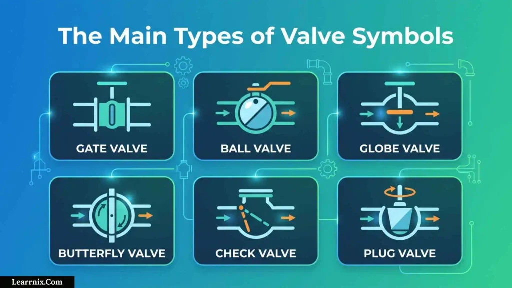
Gate valve symbols
A gate valve is commonly selected for isolation service.
Its physical closure element moves to block or open the flow passage. In normal engineering practice, gate valves are generally associated with fully open or fully closed service rather than routine throttling.
A gate valve symbol therefore often appears on process drawings at locations where equipment or pipeline sections need to be isolated.
Typical applications include:
- pipeline isolation,
- water systems,
- utility systems,
- process plants,
- steam services,
- and other applications requiring isolation.
Practical example: A pump may have an isolation valve on its suction or discharge side so the pump can be separated from the process during maintenance.
The key lesson is that the symbol tells you the valve type, while the surrounding drawing tells you why that valve is located there.
Globe valve symbols
Globe valves are commonly associated with throttling and flow regulation.
Their construction allows the closure element to move relative to a seat, making them suitable for applications where controlling flow is important.
You may find them in:
- steam systems,
- process control applications,
- utility services,
- and lines where flow adjustment is required.
A common beginner mistake is to treat a globe valve and gate valve as interchangeable because both can shut off flow.
They can both provide shutoff, but their typical design purposes and flow-control characteristics differ.
Ball valve symbols
A ball valve uses a rotating ball containing a passage.
A quarter-turn rotates the ball between open and closed positions.
Ball valves are widely used for:
- isolation,
- process lines,
- gas service,
- water systems,
- and automated on/off applications.
On a drawing, the symbol should be interpreted together with any actuator representation.
For example, a ball valve with a pneumatic actuator represents a very different operating arrangement from a manually operated ball valve, even though the basic valve body function is similar.
Butterfly valve symbols
A butterfly valve uses a rotating disc positioned inside the flow passage.
It is often used where compact construction and quarter-turn operation are desirable.
Typical applications include:
- water treatment,
- HVAC,
- cooling-water systems,
- industrial piping,
- and large-diameter pipelines.
Butterfly valves can be used for isolation and, depending on the valve design and service, control applications.
The symbol alone should not be used to assume that every butterfly valve is suitable for throttling.
Check valve symbols
A check valve is designed to permit flow in the intended direction while restricting reverse flow.
This makes the flow direction especially important when reading its symbol.
A common real-world example is a pump discharge line.
If fluid could flow backward through the pump when it stops, a check valve may be used to help prevent that reverse-flow condition.
Check valves can also appear in:
- compressor systems,
- process lines,
- water systems,
- hydraulic circuits,
- and other systems where reverse flow must be controlled.
Important distinction: A check valve is not normally operated like a manual isolation valve. Its function is generally automatic and related to the pressure/flow condition.
Plug valve symbols
Plug valves use a rotating plug with a passage through it.
They are commonly associated with quarter-turn operation and may be used for isolation or selected control services depending on design.
Applications can include:
- process piping,
- gas systems,
- chemical services,
- and industrial isolation.
When identifying a plug-valve symbol, compare it with the project legend rather than relying on a remembered drawing from another standard.
Needle valve symbols
Needle valves are associated with fine flow adjustment, particularly in smaller lines.
They are often encountered in:
- instrument connections,
- sampling arrangements,
- pressure-control applications,
- small-bore piping,
- and calibration or measurement systems.
A needle valve may be physically small but still important to the operation of an instrumentation system.
Diaphragm valve symbols
A diaphragm valve uses a flexible diaphragm to control the flow passage.
One important feature is the separation between the operating mechanism and the process fluid.
Depending on design and service, this can make diaphragm valves useful for:
- sanitary processes,
- pharmaceutical applications,
- chemical service,
- corrosive fluids,
- and contamination-sensitive systems.
The surrounding process conditions still determine whether a particular diaphragm valve is appropriate.
Valve Symbol Comparison Chart
| Valve type | Primary function | Typical operation | Common use |
| Gate | Isolation | Multi-turn | Pipeline and equipment isolation |
| Globe | Regulation/throttling | Multi-turn | Flow adjustment |
| Ball | Shutoff/isolation | Quarter-turn | Process and utility lines |
| Butterfly | Isolation/control | Quarter-turn | Large-bore piping |
| Check | Prevent reverse flow | Automatic | Pump and process lines |
| Plug | Isolation/control in selected services | Quarter-turn | Process and gas systems |
| Needle | Fine adjustment | Multi-turn | Instrument and small-bore lines |
| Diaphragm | Isolation/control | Various | Sanitary and corrosive services |
| Control valve | Automatic regulation | Actuated | Flow, pressure, temperature, level |
| Solenoid valve | Automated switching | Electromagnetic | Control and sequencing |
This is a functional comparison, not a valve-selection specification. Actual selection depends on pressure, temperature, fluid properties, materials, leakage requirements, operating conditions, and the applicable engineering specification.
How Control Valve Symbols Work
What makes a control valve different?
A conventional manual valve primarily depends on an operator to change its position.
A control valve forms part of an automatic control loop.
For example, suppose a process must maintain a target flow rate.
A typical control arrangement may involve:
Flow → measurement → controller → signal → actuator → valve position → changed flow
The valve is therefore the final control element in the loop.
The symbol needs to communicate more than simply “there is a valve here.”
Reading a control valve as a system
When examining a control valve on a P&ID, look for:
- Valve body
- Actuator
- Instrument tag
- Signal connection
- Associated transmitter or controller
- Process line
- Fail-action information, where specified
- Project notes and legend
This layered approach is more useful than memorizing an entire control-valve symbol as a single image.
A practical example
Imagine a steam line feeding a heat exchanger.
A temperature transmitter measures the outlet temperature. A controller compares the measurement with the desired setpoint. The controller sends a signal to the control valve actuator.
If more heating is required, the control system may change the valve position to alter steam flow.
The P&ID uses symbols to communicate this relationship.
The important point is that the valve symbol is part of a control story, not an isolated icon.
Understanding Valve Actuator Symbols
Manual operation
A manual valve may use:
- a handwheel,
- lever,
- handle,
- or another mechanical operator.
Manual valves are common where frequent automatic adjustment is unnecessary.
Pneumatic actuation
Pneumatic actuators use compressed air to move a valve.
They are widely used in process automation because compressed air can be distributed throughout industrial facilities.
A pneumatic actuator can operate a valve remotely based on a control signal.
Electric actuation
Electric actuators use an electrical drive system to move the valve.
They may be used where:
- remote operation is needed,
- compressed air is unavailable,
- electrical control is preferred,
- or the operating duty suits an electric actuator.
Hydraulic actuation
Hydraulic actuators use pressurized fluid to generate movement.
They can be useful when significant operating force is required.
Solenoid operation
A solenoid operator uses electromagnetic action to shift or operate a valve mechanism.
Solenoid-operated valves are common in:
- pneumatic systems,
- hydraulic systems,
- automated isolation,
- sequencing,
- and machine-control applications.
Expert tip: Do not confuse the valve type with the actuator type. A ball valve can be manually operated, pneumatically actuated, or electrically actuated. The valve body and actuator communicate different pieces of information.
P&ID Valve Symbols Explained
What is a P&ID?
A Piping and Instrumentation Diagram, commonly called a P&ID, shows the functional relationships between:
- piping,
- equipment,
- valves,
- instruments,
- control systems,
- and process connections.
It is not normally a scale drawing of the physical plant.
The purpose is to communicate how the process works and how it is measured and controlled.
ISA’s standards program includes ISA5.1 for instrumentation and control symbols and identification, along with ISA-TR5.1.04-2026 concerning content for PFDs and P&IDs.
Why valve symbols on P&IDs can look different
There is no safe rule that says every P&ID in every company will display every valve in exactly the same way.
ISA5.1 itself recognizes different organizational needs and provides options for symbolism where they remain consistent with the standard’s objectives.
A project may also define:
- its own legend,
- tag format,
- line conventions,
- actuator representation,
- abbreviations,
- and additional notes.
That is why the project legend is one of the first things you should check.
Hydraulic Valve Symbols
Hydraulic diagrams use a different graphical language from many process P&IDs.
ISO 1219-1 establishes basic elements and rules for creating fluid-power symbols used for components and circuit diagrams. It is specifically relevant to hydraulic and pneumatic systems.
Directional control valve symbols
A hydraulic directional-control valve is often represented using adjacent boxes.
Each box represents a valve position.
Arrows or other internal marks show how ports are connected in that position.
This means the symbol communicates function, rather than trying to provide a realistic picture of the valve.
Two-position directional valves
A two-position valve has two operating states.
The diagram shows both states so the reader can determine what happens when the valve shifts.
Three-position directional valves
A three-position valve has three operating states.
The center position can be especially important because it may determine what happens when the valve is not actively shifted.
For example, depending on the circuit design, the center condition may:
- block certain ports,
- connect selected ports,
- unload a pump,
- or allow another defined flow arrangement.
The exact interpretation must come from the symbol and circuit.
Springs and operators
Hydraulic symbols may also show:
- springs,
- manual operators,
- solenoids,
- pneumatic pilots,
- hydraulic pilots,
- and other control elements.
These additional marks explain how the valve changes position.
Pneumatic Valve Symbols
Pneumatic systems use the same general fluid-power graphical approach covered by ISO 1219.
A pneumatic directional valve determines where compressed air travels within a circuit.
Example: controlling a pneumatic cylinder
Suppose a manufacturing machine uses a double-acting cylinder.
The cylinder needs compressed air directed to one side to extend and to the opposite side to retract.
A directional-control valve provides those flow paths.
The symbol lets the reader determine:
- how many positions the valve has,
- how many ports are available,
- which ports connect in each position,
- whether a path is blocked,
- and how the valve is shifted.
This is why hydraulic and pneumatic symbols should be read as functional diagrams rather than pictures.
How to Read Valve Symbols Step by Step
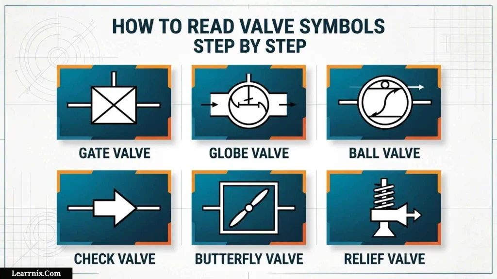
Step 1: Identify the drawing type
Ask whether you are looking at:
- a P&ID,
- process flow diagram,
- hydraulic circuit,
- pneumatic circuit,
- piping drawing,
- or another type of engineering document.
This immediately narrows the appropriate symbol system.
Step 2: Find the legend
The legend should be your first reference when a symbol is unfamiliar.
Check for:
- valve symbols,
- actuator symbols,
- line types,
- instrument symbols,
- abbreviations,
- tag conventions,
- and special project notes.
Step 3: Identify the valve body
Determine the basic valve function or type before studying the actuator.
Step 4: Identify the operator or actuator
Ask:
Who or what moves this valve?
Possible answers include:
- operator,
- pneumatic actuator,
- electric actuator,
- hydraulic actuator,
- solenoid,
- spring,
- or another mechanism.
Step 5: Follow the connected piping
Trace the line before deciding what the valve does in the process.
A valve installed upstream of a pump may have a different purpose from a similar valve located around a heat exchanger or control loop.
Step 6: Read the tag
The tag connects the symbol to other project documents.
Depending on the project, it may lead you to:
- a valve schedule,
- datasheet,
- instrument index,
- equipment list,
- specification,
- or maintenance record.
Step 7: Examine signal connections
If the valve is automated, determine whether the diagram shows a connection to a controller, transmitter, PLC, DCS, or another control device.
Step 8: Check fail-action information
For an automated valve, determine whether the documentation specifies what happens when the control signal or actuator energy is lost.
Do not guess.
A safety-related interpretation should come from the engineering documentation and approved design basis.
Decision Guide: Which Valve Symbol System Are You Looking At?
Use this simple decision process when an unfamiliar symbol appears on a drawing.
Is the drawing mainly about industrial process piping and instrumentation?
→ Check the P&ID/project convention and ISA5.1.
Is the drawing a hydraulic or pneumatic fluid-power circuit?
→ Check ISO 1219 and the project convention.
Is it a broader industrial graphical diagram?
→ Check the applicable ISO 14617 convention and project documentation.
Does the symbol still look unfamiliar?
→ Check the drawing legend.
Does the legend differ from what you remember?
→ Follow the documented project convention.
Is the interpretation safety-critical?
→ Verify against the approved engineering documentation rather than relying on visual memory.
This decision tree prevents one of the most common mistakes: applying a familiar symbol system to the wrong type of drawing.
Valve Symbols vs Valve Tags
What a symbol tells you
A symbol can communicate:
- valve type,
- operating function,
- actuator,
- control relationship,
- or flow-path information.
What a tag tells you
A tag identifies the specific item in the project.
For example, a project may assign a valve an identifier such as:
XV-101
The exact meaning of the letters depends on the project’s identification convention.
The important point is that the tag connects the drawing to the physical and documentary record.
Why both are necessary
Two valves may have similar graphical representations but perform different roles in a plant.
The symbol answers:
“What kind of function is represented here?”
The tag helps answer:
“Which actual valve is this?”
This distinction becomes critical during maintenance and troubleshooting.
Common Misconceptions About Valve Symbols
Misconception 1: There is one universal valve-symbol chart
There are multiple standards and drawing conventions.
ISA5.1 focuses on instrumentation and control documentation, ISO 1219 addresses fluid-power symbols, and ISO 14617 provides a broader industrial graphical-symbol framework.
Better approach: Identify the drawing system first.
Misconception 2: The symbol tells you the complete valve specification
It usually does not.
A symbol cannot normally replace the valve datasheet.
You may still need:
- nominal size,
- pressure class,
- material,
- trim,
- temperature range,
- connection details,
- leakage requirements,
- and actuator specifications.
Misconception 3: A valve symbol is a physical drawing
Engineering symbols are intentionally simplified.
Their purpose is communication, not physical realism.
Misconception 4: Similar-looking valves perform the same job
A gate valve, globe valve, ball valve, and butterfly valve may all be capable of stopping flow, but their designs, operating characteristics, and typical applications differ.
Misconception 5: The actuator and valve are the same thing
They are separate concepts.
The valve controls or directs the process fluid.
The actuator provides the mechanism that moves the valve when automation or remote operation is required.
Common Mistakes When Reading Valve Symbols
Ignoring the project legend
This is probably the most avoidable mistake.
A drawing legend exists specifically to explain the conventions used on that document.
Confusing hydraulic symbols with P&ID symbols
A hydraulic directional-control symbol may use boxes and internal arrows in a way that is very different from a process P&ID valve representation.
The drawing type should always be identified first.
Ignoring flow direction
This is especially important for check valves and directional-control valves.
A symbol cannot be interpreted correctly if the flow path is ignored.
Assuming a valve is normally open or normally closed
The physical position of a valve cannot always be safely inferred from the basic valve-body symbol.
Look for the project’s notation, valve schedule, actuator information, or operating documentation.
Ignoring the actuator
A manually operated valve and an automatically actuated valve can have very different operational implications.
Treating the P&ID as a physical layout
A P&ID explains functional relationships. It is not necessarily a precise representation of where components physically sit.
For physical location, use the appropriate piping arrangement, layout, or isometric documentation.
Valve Symbols in Real-World Applications
Pump systems
A typical pump installation may contain isolation and non-return functions.
A technician might use the P&ID to identify the isolation points and check valve around the pump before maintenance.
Heat exchanger systems
A heat exchanger may have valves on its inlet and outlet connections.
Additional control valves may regulate the flow of heating or cooling media.
The symbols help distinguish basic isolation from automatic control.
Water treatment plants
Water-treatment systems commonly use valves to isolate equipment, control flow, and prevent reverse flow.
Because these systems can contain many parallel lines, clear symbolic documentation is particularly useful.
Manufacturing equipment
Manufacturing machines frequently combine pneumatic and hydraulic valve symbols with electrical control systems.
A technician may therefore need to understand more than one symbol convention within the same facility.
Process control loops
A temperature-control loop may include:
Temperature sensor → transmitter → controller → control valve → process
The valve symbol represents the final control element, while the associated instrumentation explains why its position changes.
Engineering Standards for Valve and Diagram Symbols
ANSI/ISA-5.1
ANSI/ISA-5.1-2024 is an important reference for instrumentation and control symbols and identification.
ISA states that the standard establishes a uniform system for depicting and identifying instrumentation and control functions used in industrial process measurement and control. ISA also notes that the 2024 revision expanded the title to explicitly include control symbols.
ISO 1219-1
ISO 1219-1 is specifically relevant to fluid-power graphical symbols, including hydraulic and pneumatic systems.
ISO explains that the standard establishes basic elements and rules for devising symbols used on fluid-power components and circuit diagrams.
ISO 14617
ISO 14617 provides a broader graphical-symbol framework for industrial diagrams.
The current ISO 14617-1:2025 establishes general rules for preparing and presenting graphical symbols related to industrial components, products, and processing.
ISO 14617-2:2025 provides a graphical-symbol library for industrial components and processing. It also explicitly distinguishes fluid-power objects, which are covered by ISO 1219-1, and measurement/control functions that fall under other standards.
Why standards do not eliminate the need for a legend
Standards provide consistency, but engineering projects still have documentation practices and conventions.
ISA itself recognizes organizational needs and provides alternative symbolism methods within the scope of its standard.
Therefore, the best professional habit is:
Know the standard, then read the project legend.
Best Practices for Using Valve Symbols
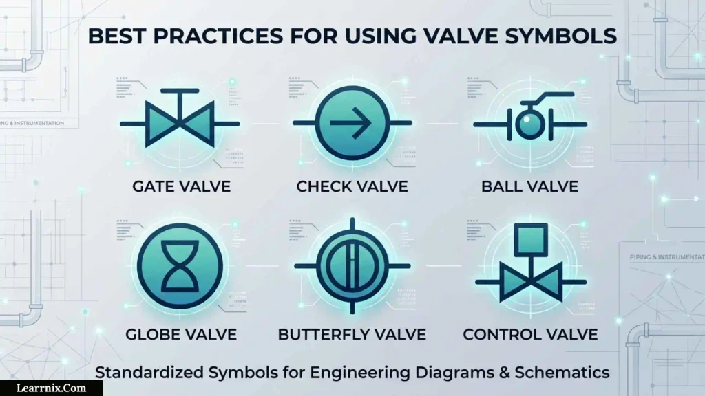
Learn functions instead of memorizing pictures
Instead of memorizing dozens of isolated graphics, learn the concepts:
- isolation,
- throttling,
- non-return,
- pressure protection,
- directional control,
- automatic regulation,
- and actuation.
This makes unfamiliar diagrams much easier to understand.
Read the entire symbol as a system
For automated valves, do not stop at the valve body.
Read:
Valve body + actuator + signal + tag + process connection + control relationship
Cross-check important interpretations
For important engineering decisions, compare the drawing with:
- valve datasheet,
- valve schedule,
- P&ID legend,
- equipment documentation,
- control narrative,
- and applicable specifications.
Use the drawing type as your starting point
This one habit eliminates many errors.
Do not assume that a symbol from a pneumatic circuit will have the same meaning on a process P&ID.
Never guess safety-related functions
If you need to know whether a valve fails open, fails closed, or remains in position, verify the approved design documentation.
A symbol should not be treated as a substitute for a safety or control-system specification.
A Practical Checklist for Identifying an Unknown Valve Symbol
Before deciding what a symbol means, ask:
- What type of drawing am I reading?
- What standard or project convention applies?
- Where is the drawing legend?
- What does the valve body represent?
- Is the valve manual or actuated?
- What type of actuator is shown?
- What is the flow direction?
- What does the valve tag identify?
- Is there an instrument or controller connected to it?
- Is there a check, spring, solenoid, or other operator?
- Does the symbol indicate a normal or fail position?
- Do the valve schedule and datasheet agree?
- Is the interpretation important enough to require formal verification?
This checklist is often more useful than trying to memorize an enormous valve-symbol chart.
Frequently Asked Questions About Valve Symbols
What is the purpose of a valve symbol?
A valve symbol provides a simplified graphical representation of a valve’s function, type, operation, or control relationship on an engineering drawing.
What are the most common valve symbols?
Common valve categories include gate, globe, ball, butterfly, check, plug, needle, diaphragm, control, and solenoid-operated valves. Hydraulic and pneumatic diagrams add directional-control and other fluid-power symbols.
What is the difference between a valve symbol and a valve tag?
The symbol communicates the component’s graphical function or type. The tag identifies the particular valve within the project.
What does a check valve symbol indicate?
It indicates a valve intended to permit flow in the intended direction and restrict reverse flow.
Which valve is commonly associated with throttling?
Globe valves are commonly associated with throttling, while control valves are specifically designed and actuated for automatic process regulation.
Are valve symbols the same on P&IDs and hydraulic drawings?
No. P&IDs use process and instrumentation conventions, while hydraulic and pneumatic diagrams use fluid-power conventions such as those established by ISO 1219-1.
What standard is used for P&ID instrumentation symbols?
ANSI/ISA-5.1 is a major reference for instrumentation and control symbols and identification in process industries. Projects may also use other applicable standards and documented conventions.
What standard is used for hydraulic valve symbols?
ISO 1219-1 is the key international reference for graphical symbols used with fluid-power systems and components, including hydraulic and pneumatic applications.
Can a valve symbol show whether a valve is normally open?
Sometimes additional notation or project conventions can communicate normal position, but the basic valve-body symbol should not automatically be assumed to provide that information. Check the legend and documentation.
Does a valve symbol show valve size?
Normally, the graphical symbol itself is not a complete specification of valve size. Size and other physical details are generally obtained from the valve tag, schedule, datasheet, or piping documentation.
How do I identify an unfamiliar valve symbol?
First identify the drawing type, then check the legend and applicable standard. After that, examine the valve body, actuator, flow direction, tag, and connected instrumentation.
Why do hydraulic valve symbols use boxes?
In fluid-power diagrams, the boxes represent different operating positions of a directional valve. Internal arrows and other marks show how ports are connected in each position.
What is the difference between a control valve and an isolation valve?
An isolation valve is primarily intended to separate or isolate part of a system. A control valve is used as part of an automatic control loop to regulate a process variable such as flow, pressure, temperature, or level.
Why are actuator symbols important?
The actuator tells you how the valve is moved. A valve with manual operation has different operational characteristics from one operated by pneumatic, electric, hydraulic, or solenoid mechanisms.
Key Takeaways
Valve symbols are a technical language for communicating how valves function within engineering systems.
The most important principles are:
- Identify the drawing type first.
- Check the project legend before relying on memory.
- Separate the valve body from the actuator.
- Follow the process or fluid-flow path.
- Read the valve tag and associated instrumentation.
- Use the appropriate standard for the application.
- Do not assume a symbol provides the complete valve specification.
- Do not confuse P&ID symbols with hydraulic or pneumatic symbols.
- Verify important or safety-related interpretations against approved documentation.
For process instrumentation and control, ANSI/ISA-5.1-2024 is an important reference. For hydraulic and pneumatic fluid-power symbols, ISO 1219-1 is directly relevant. ISO 14617 provides broader rules and symbol libraries for industrial diagrams.
The most effective way to learn valve symbols is therefore not to memorize every graphic independently. Learn the function, drawing system, symbol structure, actuator, flow path, and documentation hierarchy. Once those relationships are clear, even unfamiliar engineering diagrams become much easier to interpret.

I am Charlotte Anderson, an education writer who is passionate about creating meaningful learning resources for students and lifelong learners.
I enjoy researching new educational approaches and sharing ideas that make studying easier and more effective.
Through my work, I aim to inspire curiosity, confidence, and a love for learning.
Books:
- The Complete Guide to Better Learning
- Building Skills for Academic Success
 Michael Carter
 Daniel Harper