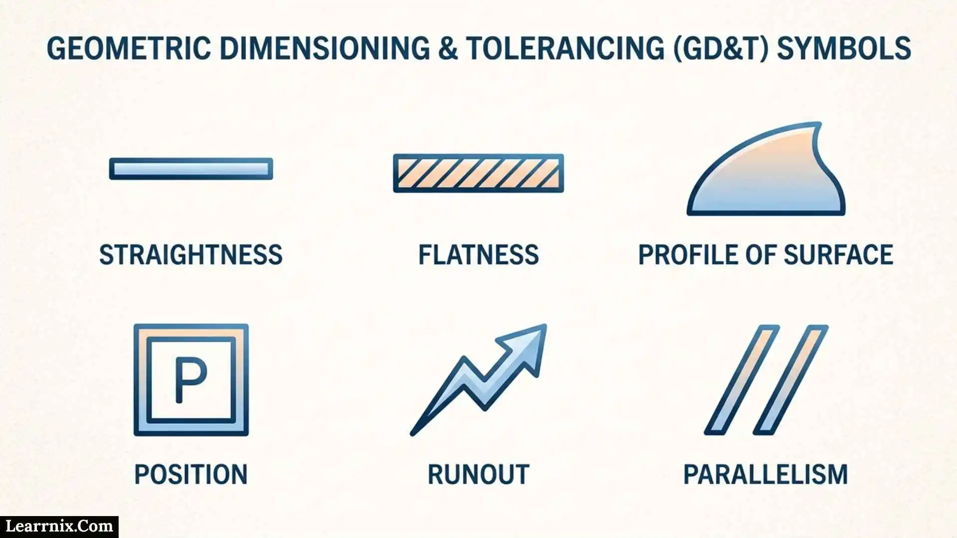
GD&T symbols are a standardized visual language used on engineering drawings, CAD models, and related product documentation to communicate how much a feature is allowed to vary from its intended geometry, location, orientation, or form.
GD&T stands for Geometric Dimensioning and Tolerancing. Instead of describing every manufacturing requirement with long notes, engineers use standardized symbols, tolerance values, datum references, and modifiers to define design intent clearly.
The current ASME framework is ASME Y14.5-2018, which establishes standardized practices for dimensioning and tolerancing. ASME describes Y14.5 as the authoritative guideline for the GD&T design language and emphasizes its role in communicating and interpreting engineering requirements.
For someone learning GD&T, the symbols can initially look confusing. However, they become much easier once you understand what each category controls and how the symbols work inside a feature control frame.
This guide explains:
- What GD&T symbols mean
- The major categories of geometric controls
- The current GD&T symbol set
- Form, orientation, location, profile, and runout controls
- Datum symbols and datum reference frames
- Feature control frames
- MMC, LMC, and RFS
- Basic dimensions and tolerance zones
- Practical engineering examples
- Common mistakes
- How to choose the right GD&T control
- How GD&T is used in manufacturing and inspection
- Frequently asked questions
Quick Answer: What Are GD&T Symbols?
GD&T symbols are standardized symbols used to specify geometric requirements on engineering drawings and digital product definitions.
The main geometric characteristic groups in ASME Y14.5 are:
| Category | Controls | Examples |
| Form | Shape of individual features | Straightness, flatness, circularity, cylindricity |
| Orientation | Direction relative to a reference | Angularity, perpendicularity, parallelism |
| Location | Where a feature is positioned | Position |
| Profile | Shape of lines or surfaces | Profile of a line, profile of a surface |
| Runout | Variation during rotation | Circular runout, total runout |
A complete GD&T requirement normally combines a geometric characteristic symbol with a tolerance value and, where required, datum references and material-condition modifiers.
ASME’s current Y14.5-based educational material covers these major areas, including datums, form, orientation, position, profile, and runout.
What Does GD&T Mean?
Definition of GD&T
Geometric Dimensioning and Tolerancing is a system for defining allowable variation in the geometry of manufactured parts.
Traditional plus/minus tolerancing mainly tells you how large or small a feature can be. GD&T goes further by controlling relationships such as:
- Whether a surface is flat
- Whether a hole is correctly positioned
- Whether a shaft is straight
- Whether two surfaces are perpendicular
- Whether a cylindrical surface has excessive runout
- Whether a complex surface follows its intended profile
This allows a drawing to communicate functional design intent, rather than simply listing measurements.
Why GD&T Is Used
A mechanical component rarely works because every dimension is exactly equal to its nominal value. Real manufacturing always introduces variation.
The important question is therefore not simply:
“Is this dimension exact?”
Instead, engineers need to know:
“How much variation can this feature have while the part still performs its intended function?”
GD&T provides a structured way to answer that question.
ASME explains that GD&T provides a common language across product realization, including design, manufacturing, and inspection.
The Five Main GD&T Symbol Categories

1. Form Controls
Form controls define the shape of an individual feature.
The four primary form controls are:
- Straightness
- Flatness
- Circularity
- Cylindricity
Form controls generally focus on the feature itself rather than its relationship to another feature.
2. Orientation Controls
Orientation controls define how a feature is oriented relative to a datum or reference.
They include:
- Angularity
- Perpendicularity
- Parallelism
For example, a perpendicularity requirement can control whether a surface or axis remains at the required 90-degree relationship to a datum.
3. Location Control
The principal location characteristic is:
- Position
Position controls the location of a feature relative to theoretically exact locations and applicable datum references.
It is especially important for hole patterns, mounting features, shafts, and other features whose location affects assembly.
4. Profile Controls
Profile controls manage the shape of a line or surface.
They include:
- Profile of a line
- Profile of a surface
Profile controls are particularly useful for curved, contoured, or complex surfaces.
5. Runout Controls
Runout controls are associated with rotational features.
They include:
- Circular runout
- Total runout
Runout is commonly important for rotating components such as shafts, wheels, hubs, and precision cylindrical surfaces.
GD&T Form Symbols
Straightness
Straightness controls how much a line element or derived feature can deviate from perfect straightness.
Imagine a long shaft that is supposed to be straight. Its surface may appear visually straight but still contain small bends.
A straightness requirement limits that deviation.
Straightness Example
Suppose a shaft has a straightness requirement of 0.05 mm.
The controlled line or derived feature must remain within the specified straightness tolerance zone according to the applicable GD&T rules.
Straightness is useful when bending or bowing could interfere with:
- Assembly
- Movement
- Sealing
- Bearing operation
- Contact between components
Flatness
Flatness controls how much a surface can deviate from a perfectly flat plane.
A flatness tolerance creates a zone between two parallel planes.
For example, a mounting surface might require a flatness tolerance of 0.03 mm.
This does not necessarily mean the surface must be exactly at a particular location. Instead, the surface must remain within the permitted flatness zone.
This distinction is important: flatness controls form, not orientation to a datum.
Circularity
Circularity, also called roundness, controls the form of individual circular cross-sections.
It limits how much each circular element can deviate from the required circular form.
Circularity can matter when manufacturing:
- Shafts
- Pins
- Bearings
- Holes
- Cylindrical sealing surfaces
Circularity should not be confused with cylindricity. Circularity evaluates circular sections, while cylindricity controls the overall cylindrical form.
Cylindricity
Cylindricity controls the overall form of a cylindrical surface.
It considers the cylindrical feature as a whole rather than checking individual circular sections independently.
For a precision shaft, cylindricity can help control combined variations in the cylindrical surface.
A useful way to remember the difference is:
Circularity = individual round cross-sections
Cylindricity = complete cylindrical form
GD&T Orientation Symbols
Angularity
Angularity controls the orientation of a feature to a specified basic angle.
The required angle is established by a basic dimension or other applicable drawing information.
Angularity is useful when a surface must be positioned at an angle other than 90 or 0 degrees relative to a datum.
For example, an angled mounting surface could have an angularity requirement relative to a datum plane.
Perpendicularity
Perpendicularity controls whether a feature is oriented at 90 degrees relative to a datum.
It is widely useful for:
- Mounting surfaces
- Holes
- Shafts
- Machined faces
- Structural features
For example, if a hole must be perpendicular to a mounting surface, the mounting surface can establish the datum while the hole’s orientation is controlled relative to it.
Perpendicularity does not primarily control the location of the feature. It controls its orientation.
Parallelism
Parallelism controls whether a feature remains parallel to a specified datum or reference.
Consider two machined surfaces that need to remain parallel for proper assembly. A parallelism requirement can control their orientation.
Like flatness, parallelism involves a controlled tolerance zone, but the critical difference is that parallelism establishes orientation relative to a datum.
GD&T Position Symbol
Position
Position is one of the most important location controls in GD&T.
Position controls the location of a feature relative to theoretically exact dimensions and applicable datum references.
It is frequently used for:
- Holes
- Pins
- Slots
- Tabs
- Patterns of features
- Cylindrical features
For example, suppose a plate contains four mounting holes.
A traditional drawing might provide separate horizontal and vertical dimensions for every hole. GD&T position can define the intended hole locations through basic dimensions and a positional tolerance.
This can make the drawing easier to interpret and can provide a clearer connection between the hole pattern and its functional requirements.
ASME’s GD&T training specifically includes position calculations, datum reference frames, and applications involving fixed and floating fasteners and coaxial relationships.
GD&T Profile Symbols
Profile of a Line
The profile of a line controls the shape of a feature in a two-dimensional cross-section.
Imagine the cross-section of a curved component. Instead of controlling several individual dimensions, the profile can establish a controlled boundary around the intended curve.
This is useful for:
- Curved edges
- Contoured sections
- Molded components
- Machined profiles
- Airfoil-like shapes
Profile of a Surface
Profile of a surface controls a three-dimensional surface.
It is especially useful when the entire surface must follow a complex design shape.
Applications can include:
- Automotive body surfaces
- Cast components
- Molded plastic parts
- Aerospace contours
- Complex machined surfaces
- CAD-defined surfaces
Profile can provide a powerful way to control complex geometry without filling a drawing with numerous individual dimensions.
GD&T Runout Symbols
Circular Runout
Circular runout controls variation at individual circular cross-sections as a feature is rotated around a specified datum axis.
It can be useful for rotating components where excessive variation could cause:
- Vibration
- Uneven contact
- Seal problems
- Noise
- Poor rotational performance
A common application is a rotating shaft or cylindrical surface.
Total Runout
Total runout provides a broader control over the entire surface during rotation.
Instead of focusing on individual circular sections, total runout evaluates variation across the controlled surface as the part rotates relative to the applicable datum axis.
It can be useful when both surface form and rotational behavior are important.
A simple distinction is:
Circular runout = local rotational variation
Total runout = overall rotational variation across the surface
ASME’s Y14.5 structure specifically includes runout as a major area of the standard, alongside form, orientation, position, and profile.
Datum Symbols in GD&T
What Is a Datum?
A datum is a theoretically exact reference used to establish a relationship for measurement and geometric control.
Think of a datum as the reference framework from which other requirements are evaluated.
For example:
- A flat bottom surface can establish a primary datum.
- A side surface can establish a secondary datum.
- Another feature can establish a tertiary datum.
The exact selection depends on the part’s functional requirements.
Primary, Secondary, and Tertiary Datums
A datum reference frame commonly uses three levels:
- Primary datum
- Secondary datum
- Tertiary datum
The purpose is to establish a stable reference system that constrains the part appropriately.
The primary datum establishes the first major reference relationship. The secondary datum adds another constraint, while the tertiary datum completes the reference framework.
The important engineering principle is that datums should be selected according to how the part functions, assembles, and is inspected, rather than simply choosing convenient surfaces.
ASME training specifically emphasizes proper datum reference-frame selection and datum relationships.
How to Read a GD&T Feature Control Frame
A feature control frame contains the information needed to communicate a geometric requirement.
It can contain:
- Geometric characteristic symbol
- Tolerance value
- Diameter symbol when applicable
- Material-condition modifier
- Datum references
A simplified conceptual example might look like:
[Position] | ⌀0.10 | A | B | C
The meaning depends on the exact feature, modifiers, and drawing context, but the general interpretation is:
- The geometric control is position.
- The tolerance zone has a specified diameter.
- Datum A establishes the primary reference.
- Datum B establishes the secondary reference.
- Datum C establishes the tertiary reference.
How to Read a Feature Control Frame Step by Step
Start by identifying the geometric characteristic.
Next, read the tolerance value.
Then check whether a diameter symbol appears.
After that, look for modifiers such as MMC or LMC.
Finally, identify the datum references and their order.
This sequence makes complex drawing notes much easier to interpret.
GD&T Modifiers: MMC, LMC, and RFS
Maximum Material Condition
MMC means Maximum Material Condition.
For an external feature such as a shaft, MMC corresponds to the largest permitted size.
For an internal feature such as a hole, MMC corresponds to the smallest permitted size.
MMC can be important when functional assembly and additional positional tolerance are involved.
Least Material Condition
LMC means Least Material Condition.
It represents the size condition in which the feature contains the least amount of material within its applicable size limits.
LMC can be useful when minimum wall thickness or other material-related functional requirements are important.
Regardless of Feature Size
RFS means Regardless of Feature Size.
Under RFS, the geometric tolerance applies independently of the actual size of the feature unless another applicable rule or modifier changes that relationship.
Understanding MMC, LMC, and RFS is essential because the same geometric tolerance value can have different functional consequences depending on the modifier.
Basic Dimensions and GD&T
A basic dimension represents the theoretically exact location, size, angle, or other geometric relationship.
In GD&T, basic dimensions are often used together with a geometric tolerance.
For example, a hole pattern may have basic dimensions defining the exact theoretical locations, while a position tolerance defines the permissible variation around those locations.
This is different from simply applying a plus/minus tolerance to each coordinate.
The combination allows engineers to separate:
- Theoretical exact location
- Permitted geometric variation
- Functional relationships
GD&T Symbols vs. Traditional Plus/Minus Tolerancing
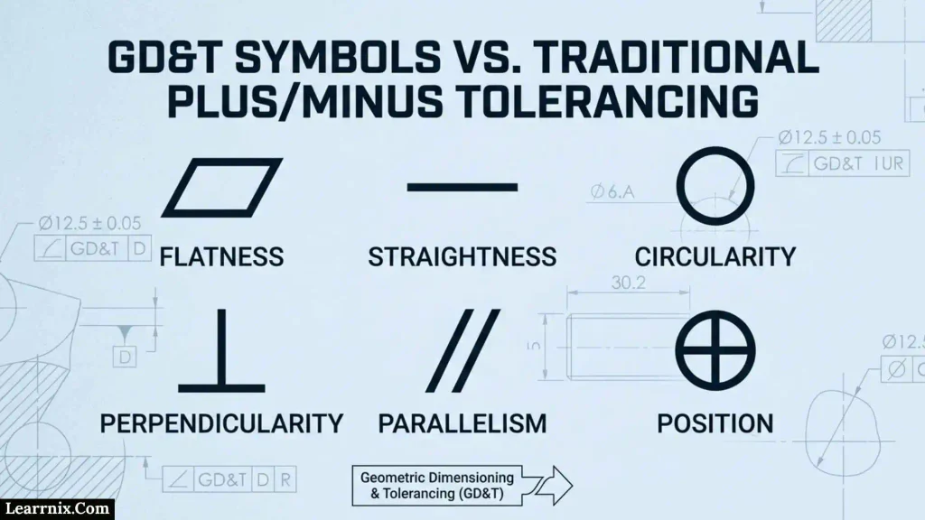
Traditional Dimensioning
Traditional tolerancing might specify:
50.00 ± 0.10 mm
This tells the manufacturer that the dimension can vary within the specified limits.
But a dimensional tolerance does not automatically describe every aspect of geometric form, orientation, and location.
GD&T
GD&T can separately communicate requirements for:
- Form
- Orientation
- Location
- Profile
- Runout
This makes it possible to define what variation actually matters to the part’s function.
Which System Should You Use?
The answer depends on the design requirement.
Use a simple dimensional tolerance when a basic size requirement is sufficient.
Use GD&T when geometric relationships, assembly, interchangeability, orientation, or functional variation need clearer control.
In practice, engineering drawings often use both dimensional tolerancing and GD&T rather than treating them as competing systems.
Practical GD&T Examples
Example 1: Mounting Holes
Imagine a metal plate with four holes used to attach another component.
The hole diameters control whether the fasteners fit.
But diameter alone does not guarantee that the holes are correctly positioned.
A position tolerance can control the hole locations relative to the selected datum reference frame.
Example 2: Machined Mounting Surface
Suppose a component must sit against another precision surface.
Flatness may be applied to the mounting surface to limit its form variation.
If the surface must also maintain a particular relationship to another datum, an orientation control may be appropriate.
This shows why engineers should not automatically choose flatness whenever a surface “needs to be flat.” The actual functional requirement determines the correct control.
Example 3: Rotating Shaft
A shaft used with bearings may require controls for:
- Straightness
- Cylindricity
- Position
- Runout
The correct combination depends on the functional relationship between the shaft, bearings, mating components, and datum system.
Example 4: Complex Curved Surface
A complex molded or machined surface may be difficult to describe using many individual dimensions.
A profile of a surface requirement can provide a more direct way to communicate the intended three-dimensional geometry.
Common GD&T Mistakes
Mistake 1: Memorizing Symbols Without Understanding Tolerance Zones
Knowing that a symbol means “flatness” is not enough.
You also need to understand what geometric zone the tolerance creates and what feature is being evaluated.
Mistake 2: Confusing Flatness and Parallelism
Flatness controls the form of a surface.
Parallelism controls orientation relative to a datum.
They may look similar in application, but they answer different engineering questions.
Mistake 3: Confusing Circularity and Cylindricity
Circularity evaluates circular sections.
Cylindricity controls the overall cylindrical form.
Using one when the other is functionally required can result in an inappropriate specification.
Mistake 4: Treating Position as a Simple Coordinate Tolerance
Position is not merely a replacement for X and Y dimensions.
It defines a geometric tolerance zone around a theoretically exact location, with the interpretation depending on the feature and applicable modifiers.
Mistake 5: Choosing Datums for Convenience
A datum should normally reflect how the part is functionally located, assembled, manufactured, or inspected.
Choosing an arbitrary surface because it is easy to measure can produce a poor datum reference frame.
Mistake 6: Ignoring Material Condition Modifiers
MMC and LMC can significantly affect how a geometric tolerance is interpreted.
A drawing reader should always inspect the feature control frame for modifiers before evaluating the requirement.
Mistake 7: Using Too Much GD&T
GD&T is powerful, but adding controls without a functional reason can make drawings unnecessarily complicated.
The goal is not to use the maximum number of symbols.
The goal is to communicate the required function clearly.
How to Choose the Right GD&T Symbol
A useful decision process is to start with the engineering problem rather than the symbol.
GD&T Decision Guide
Does the problem involve the shape of one feature?
→ Consider form controls.
Does the problem involve the direction of a feature relative to another feature?
→ Consider orientation controls.
Does the problem involve where a feature must be located?
→ Consider position.
Does the problem involve a complex curved or contoured surface?
→ Consider profile.
Does the feature rotate and require control during rotation?
→ Consider runout.
This approach is more reliable than trying to select a symbol from memory.
GD&T in Manufacturing and Inspection
GD&T is not only a drafting language. It affects the entire product-development process.
A requirement may be created by a designer, interpreted by a manufacturing engineer, produced on the shop floor, and then verified by quality personnel.
That is why consistent interpretation matters.
ASME describes GD&T as a common language across product realization and provides training that covers design, production, tooling, inspection, and related activities.
Manufacturing Applications
GD&T can help define requirements for:
- CNC-machined components
- Automotive parts
- Aerospace components
- Industrial machinery
- Tooling
- Fixtures
- Medical-device components
- Precision instruments
- Castings
- Molded parts
Inspection Applications
Inspection personnel may use:
- Coordinate measuring machines
- Optical measurement systems
- Dedicated gauges
- Fixtures
- Surface measurement equipment
- Conventional precision instruments
ASME also maintains Y14.43 for gaging principles related to the practical verification of GD&T requirements, while noting that Y14.5 itself is not a gaging standard.
GD&T Symbols Cheat Sheet
| Symbol Group | Control | Main Purpose |
| Form | Straightness | Controls straightness |
| Form | Flatness | Controls surface flatness |
| Form | Circularity | Controls roundness |
| Form | Cylindricity | Controls cylindrical form |
| Orientation | Angularity | Controls specified angular orientation |
| Orientation | Perpendicularity | Controls 90° orientation |
| Orientation | Parallelism | Controls parallel orientation |
| Location | Position | Controls feature location |
| Profile | Profile of a line | Controls a 2D profile |
| Profile | Profile of a surface | Controls a 3D surface |
| Runout | Circular runout | Controls local rotational variation |
| Runout | Total runout | Controls overall rotational variation |
What About Concentricity and Symmetry?
Older GD&T references may show concentricity and symmetry, which can cause confusion for people comparing different symbol charts.
When studying modern ASME Y14.5 material, it is important to check which revision the reference follows rather than assuming every symbol chart represents the same edition.
For current engineering work, always follow the standard and revision specified by the drawing, contract, company procedure, or applicable industry requirement.
GD&T Symbols and CAD Models
Modern product definition increasingly involves digital models rather than traditional paper-only drawings.
GD&T can be represented within model-based product-definition workflows so that manufacturing and inspection teams can interpret functional requirements more consistently.
ASME’s GD&T materials specifically discuss the use of GD&T with engineering drawings and computer-generated models.
This is important because the goal of GD&T is not simply to place symbols on a drawing. The goal is to communicate engineering intent accurately throughout the product lifecycle.
Why GD&T Improves Engineering Communication
Without a standardized system, engineers could describe the same requirement in different ways.
GD&T provides common terminology and symbols for communicating geometric requirements.
That can reduce ambiguity between:
- Design engineers
- Drafting teams
- Manufacturing engineers
- CNC programmers
- Tool designers
- Quality engineers
- Inspectors
- Suppliers
The benefit is particularly important when different teams or organizations work on the same component.
ASME describes uniform practices for stating and interpreting GD&T as an important part of manufacturing and product realization.
Beginner Checklist for Reading GD&T Drawings

Before interpreting a GD&T requirement, check the following:
- Identify the controlled feature.
- Identify the geometric characteristic.
- Read the tolerance value.
- Check for a diameter symbol.
- Look for MMC, LMC, or RFS.
- Identify datum references.
- Check the order of datum references.
- Look for basic dimensions.
- Determine the tolerance zone.
- Consider the functional purpose of the requirement.
- Confirm which ASME revision or drawing standard applies.
- Follow the complete drawing rather than interpreting one symbol in isolation.
This checklist helps prevent many beginner errors.
Frequently Asked Questions
What are GD&T symbols?
GD&T symbols are standardized graphical symbols used to communicate geometric requirements such as form, orientation, location, profile, and runout on engineering drawings and related product definitions.
How many main GD&T geometric characteristics are there?
Under the modern ASME Y14.5 framework, the geometric characteristics are organized into form, orientation, location, profile, and runout groups. Together, these groups cover the commonly taught current set of geometric characteristic symbols.
What are the four form controls in GD&T?
The four form controls are:
- Straightness
- Flatness
- Circularity
- Cylindricity
They control the form or shape of features.
What is the most important GD&T symbol for hole location?
The position control is commonly used to control the location of holes and other features of size. The correct application depends on the functional requirements and datum reference frame.
What is the difference between flatness and parallelism?
Flatness controls the form of a surface without requiring a datum reference.
Parallelism controls the orientation of a feature relative to a datum.
What is the difference between circularity and cylindricity?
Circularity controls the roundness of individual circular sections.
Cylindricity controls the overall form of a cylindrical feature.
What does MMC mean in GD&T?
MMC means Maximum Material Condition. It describes the size condition in which a feature contains the maximum amount of material within its applicable size limits.
What does RFS mean in GD&T?
RFS means Regardless of Feature Size. It means the geometric tolerance applies regardless of the actual size of the feature unless another applicable rule or modifier changes that requirement.
What is a datum in GD&T?
A datum is a theoretically exact reference used to establish a reference framework for evaluating geometric requirements.
What is a feature control frame?
A feature control frame is a standardized compartmented notation that communicates a geometric characteristic, tolerance, modifiers, and datum references when applicable.
Is GD&T difficult to learn?
The symbols themselves can be memorized fairly quickly. The more difficult part is understanding tolerance zones, datums, material conditions, feature relationships, and functional design intent.
A good learning path is to understand the categories first, then form controls, orientation, position, profile, runout, datums, and finally modifiers and more advanced applications.
Which GD&T standard should I learn?
For work based on the ASME system, ASME Y14.5-2018 is the key reference associated with the current Y14.5 framework used in the sources discussed here. ASME offers current educational material specifically based on Y14.5-2018.
However, always verify the standard and revision explicitly required by your employer, customer, contract, drawing, or industry.
Key Takeaways
GD&T symbols provide a standardized way to communicate geometric requirements that ordinary dimensional tolerances may not fully describe.
The major groups are:
- Form — straightness, flatness, circularity, and cylindricity
- Orientation — angularity, perpendicularity, and parallelism
- Location — position
- Profile — profile of a line and profile of a surface
- Runout — circular runout and total runout
To interpret GD&T correctly, however, learning the symbols is only the beginning.
You also need to understand:
- Datum reference frames
- Feature control frames
- Basic dimensions
- Tolerance zones
- MMC
- LMC
- RFS
- Feature relationships
- Functional design intent
- Inspection requirements
The best GD&T specification is not necessarily the one with the most controls. It is the one that communicates the functional requirements of the part clearly, consistently, and measurably.
Conclusion
Understanding GD&T symbols is essential for anyone who reads, creates, manufactures, or inspects mechanical engineering drawings.
The symbols provide a compact language for describing form, orientation, location, profile, and runout. But their real value comes from how they work together with dimensions, datums, tolerance zones, feature control frames, and material-condition principles.
For beginners, the most effective approach is to learn the five major categories first. Then study each symbol through real engineering examples rather than memorizing definitions alone.
Once you understand what is being controlled, what the tolerance zone looks like, what datum establishes the reference, and why the requirement exists, GD&T drawings become much easier to read.
The ultimate purpose of GD&T is simple: communicate design intent clearly enough that a part can be manufactured and inspected while still performing its intended function.

I am Charlotte Anderson, an education writer who is passionate about creating meaningful learning resources for students and lifelong learners.
I enjoy researching new educational approaches and sharing ideas that make studying easier and more effective.
Through my work, I aim to inspire curiosity, confidence, and a love for learning.
Books:
- The Complete Guide to Better Learning
- Building Skills for Academic Success
 Michael Carter
 Daniel Harper