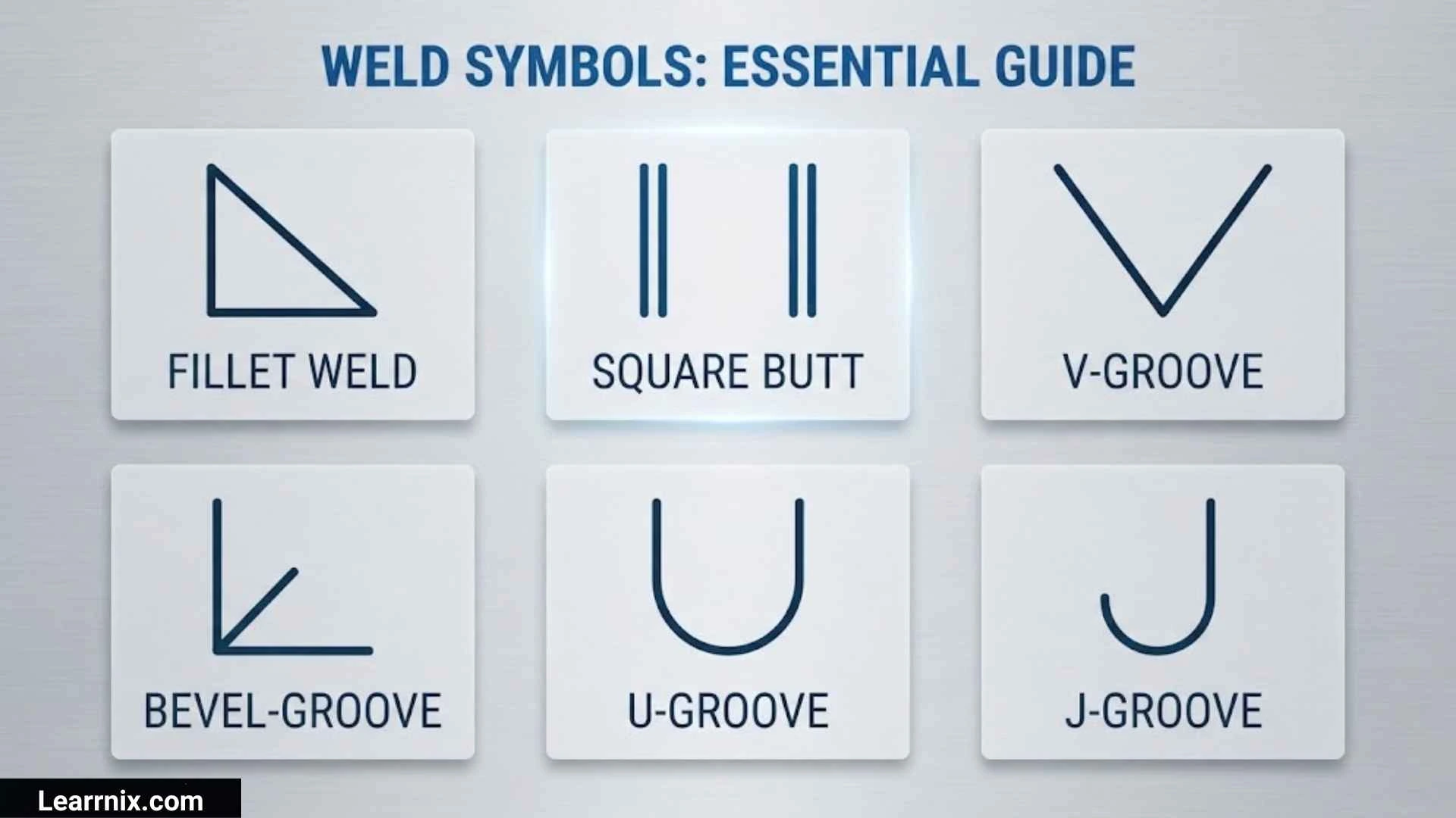
Weld symbols are a visual language used on engineering, fabrication, manufacturing, and construction drawings to communicate welding requirements clearly. Instead of describing every weld in words, a standardized symbol can show the weld type, location, size, length, and other important details.
For beginners, welding symbols can look confusing because a small mark, line, arrow, or number can change the meaning of the entire instruction. Understanding the most common weld symbols makes technical drawings much easier to read and helps prevent mistakes during fabrication.
This guide explains weld symbols from the basics to more advanced details. It covers their meanings, common types, fillet and groove weld symbols, AWS and ISO conventions, drawing interpretation, examples, and practical tips for understanding welding callouts correctly.
Weld Symbols and Meanings
Weld symbols identify the type of weld required on a joint. A complete welding symbol can contain a reference line, arrow, basic weld symbol, dimensions, supplementary symbols, and sometimes a tail containing additional information.
Some common welding symbols and their general meanings include:
| Weld Type | Basic Symbol/Form | General Meaning |
| Fillet weld | △ | Indicates a fillet weld |
| Square groove | □ | Indicates a square groove weld |
| V-groove | V-shaped symbol | Indicates a V-groove preparation |
| Bevel groove | Bevel-shaped symbol | Indicates a bevel groove |
| U-groove | U-shaped symbol | Indicates a U-groove |
| J-groove | J-shaped symbol | Indicates a J-groove |
| Plug weld | Plug-weld symbol | Indicates a weld made through a hole |
| Slot weld | Slot-weld symbol | Indicates a weld made through an elongated opening |
| Spot weld | Spot-weld symbol | Indicates a spot-welding requirement |
| Seam weld | Seam-weld symbol | Indicates a seam-welding requirement |
| Edge weld | Edge-weld symbol | Indicates an edge weld |
The symbol alone may not provide the complete welding requirement. Numbers beside or around the symbol can specify dimensions, while additional marks can communicate contour, finish, spacing, or other requirements.
Basic Weld Symbols
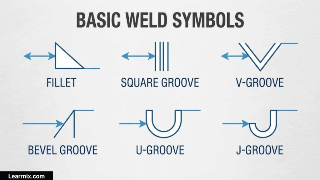
Basic weld symbols represent fundamental weld configurations used on technical drawings. Learning these symbols first gives beginners a foundation for understanding more complicated welding callouts.
The most frequently encountered basic categories include fillet, square groove, V-groove, bevel groove, U-groove, J-groove, flare-V, flare-bevel, plug, slot, spot, seam, and edge weld symbols.
A fillet weld is commonly used when two members meet at an angle. A groove weld is made in a groove between members and may require edge preparation before welding.
It is useful to remember that the symbol represents the required weld configuration, not necessarily the complete welding procedure. Welding process, electrode, shielding gas, material specifications, preheat, inspection requirements, and other information may be provided elsewhere in the drawing or specification.
Types Of Weld Symbols
Weld symbols can be organized into several groups based on the type of joint or welding operation they represent.
Plug And Slot Weld Symbols
Plug and slot welds join components through holes or elongated openings in one member. Their symbols communicate the type of opening and associated requirements.
Spot And Seam Weld Symbols
Spot and seam symbols are particularly relevant to resistance welding applications. They can communicate requirements such as weld location, number, spacing, or dimensions depending on the applicable standard.
The exact appearance and interpretation of these symbols should always be based on the standard specified by the drawing.
Common Weld Symbols
Some weld symbols appear repeatedly across mechanical, structural, automotive, fabrication, and manufacturing drawings.
The fillet weld is especially common because it provides a practical way to join members that meet at an angle. Groove welds are also widely used when stronger or full-penetration joint designs require prepared edges.
Other common symbols identify plug, slot, spot, seam, and edge welds. Supplementary symbols can also appear with these basic symbols to provide information about the finished weld.
When reading a drawing, do not interpret the basic symbol by itself. A complete welding callout may include dimensions, length, pitch, contour, finish, field-weld information, or references to a welding procedure.
Weld Symbols Chart With Examples
A quick chart is useful when learning to recognize welding symbols.
| Symbol Category | What It Indicates | Typical Example |
| Fillet | Fillet weld | T-joint |
| Square groove | Square groove joint | Two square edges joined together |
| V-groove | V-shaped groove | Prepared butt joint |
| Bevel groove | One-sided bevel preparation | Butt joint with one beveled member |
| U-groove | U-shaped preparation | Thick-section joint |
| J-groove | J-shaped preparation | Specialized groove joint |
| Plug | Weld through a circular opening | Lap-type connection |
| Slot | Weld through an elongated opening | Structural or sheet-metal connection |
| Spot | Individual resistance weld | Sheet-metal assembly |
| Seam | Continuous or intermittent resistance weld | Overlapping sheet-metal joint |
| Edge | Weld along edges | Edge-to-edge applications |
For example, a fillet weld symbol accompanied by a dimensional value can specify the required fillet size. An intermittent fillet weld may include information describing individual weld length and pitch.
These examples are intended to explain the concept. Formal drawings should always be interpreted using the applicable welding-symbol standard rather than relying on a simplified chart alone.
Weld Symbols Explained
A complete welding symbol is made from several possible elements. Understanding each element makes complicated drawings much easier to interpret.
Reference line: The horizontal reference line is the main framework of many welding symbols.
Arrow: The arrow connects the reference line to the joint or location being referenced.
Basic weld symbol: This identifies the type of weld required, such as a fillet or groove weld.
Dimensions: Numbers can communicate weld size, length, pitch, groove dimensions, or other measurements.
Tail: A tail may provide additional information, such as a specification, welding process, or reference to another document.
Supplementary symbols: These can communicate requirements related to contour, finish, all-around welding, field welding, or other characteristics.
For example, a fillet symbol tells the fabricator that a fillet weld is required. A number placed in the appropriate location can provide the required weld size, while additional dimensions can communicate length or spacing.
Understanding Weld Symbols
The easiest way to understand weld symbols is to read them as a complete instruction rather than as isolated characters.
First identify the reference line and arrow. Next determine the basic weld symbol. Then examine all dimensions and supplementary marks around it.
A common mistake among beginners is to recognize a familiar symbol and immediately assume its meaning without checking the rest of the callout. A fillet symbol, for example, does not by itself tell you every detail about the weld.
You should also check the drawing title block, notes, specifications, and referenced standards. This is particularly important when a drawing comes from another country or organization because AWS and ISO conventions are not identical in every respect.
How To Read Weld Symbols
You can use a simple sequence to interpret most welding callouts.
Step 1: Identify The Reference Line
Find the main horizontal reference line. This is the starting point for understanding the welding information.
Step 2: Follow The Arrow
The arrow points toward the joint or area associated with the welding requirement.
Step 3: Identify The Weld Type
Look at the basic symbol and determine whether it represents a fillet, groove, plug, slot, spot, seam, edge, or another weld.
Step 4: Read The Dimensions
Check numbers associated with the symbol. Depending on their location and the applicable standard, they may describe weld size, length, pitch, groove angle, root opening, or other dimensions.
Step 5: Check Supplementary Symbols
Look for contour, finish, all-around, field-weld, or other supplementary information.
Step 6: Check The Applicable Standard
Determine whether the drawing follows AWS, ISO, or another welding-symbol system. This step is essential when interpreting unfamiliar drawings.
This systematic approach is much safer than trying to memorize every possible welding callout.
Weld Symbols On Drawings
Weld symbols on drawings allow engineers and fabricators to communicate welding requirements without filling the drawing with lengthy written instructions.
They can appear on:
- Mechanical drawings
- Structural drawings
- Fabrication drawings
- Manufacturing drawings
- Assembly drawings
- Automotive drawings
- Sheet-metal drawings
- Equipment drawings
A single drawing may contain many different welding symbols. One joint may require a continuous fillet weld, while another may use an intermittent weld with a specified length and pitch.
Weld symbols can also be combined with dimensions and notes. Therefore, the symbol should always be read together with nearby annotations.
The drawing standard is equally important. A symbol interpreted under an AWS convention should not automatically be interpreted in exactly the same way on an ISO-based drawing.
Fillet Weld Symbol
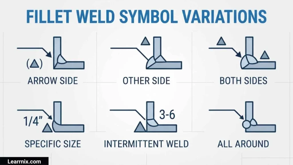
The fillet weld symbol is one of the most important symbols to recognize. It represents a fillet weld, which commonly joins two surfaces meeting at an angle.
A simple visual representation is often shown as △, but this should be understood as an explanatory representation rather than a universal Unicode replacement for the formal engineering symbol.
Fillet welds are frequently used on T-joints, lap joints, and corner joints. Their dimensions can be specified on the drawing, allowing the fabricator to understand the required weld size.
The location of the fillet symbol relative to the reference line is also significant under standards such as AWS A2.4. Therefore, identifying the triangle alone is not enough to interpret the complete requirement.
Fillet Weld Symbols
Fillet weld symbols can communicate several different requirements depending on the information included around them.
A drawing may specify:
- Fillet weld size
- Weld length
- Intermittent weld spacing
- Welds on one side
- Welds on both sides
- Continuous welding
- Contour or finish requirements
For intermittent welds, the drawing can communicate the length of individual weld segments and the pitch between them. This prevents the fabricator from assuming that the entire joint must be welded continuously.
When two fillet weld symbols appear on opposite sides of the reference line, they can communicate welding requirements on both sides of the joint under the applicable standard.
Groove Weld Symbols
Groove weld symbols describe welds made in a groove between two members. They are particularly important when the edges of the members require preparation.
Common groove configurations include:
- Square groove
- V-groove
- Bevel groove
- U-groove
- J-groove
- Flare-V groove
- Flare-bevel groove
Groove weld callouts may include additional dimensions such as groove angle, root opening, depth of preparation, or weld size.
For thicker materials, the joint preparation can have a major effect on welding access, penetration, and the amount of filler metal required. For that reason, groove symbols often need more careful interpretation than a basic fillet symbol.
AWS Weld Symbols
AWS welding symbols are commonly associated with AWS A2.4, Standard Symbols for Welding, Brazing, and Nondestructive Examination.
An AWS-style welding symbol can use a reference line, arrow, basic weld symbol, dimensions, supplementary symbols, and a tail. The relationship between the symbol and reference line is important when determining the applicable side of the joint.
AWS conventions are widely encountered in American engineering and fabrication work. However, a drawing may reference a different standard, so it is not safe to assume that every welding symbol follows AWS rules.
For detailed fabrication work, the standard identified by the drawing should always be treated as the controlling reference.
ANSI Weld Symbols
The phrase “ANSI weld symbols” is often used when discussing American welding and engineering drawing conventions. AWS welding-symbol standards are particularly important in this area.
Rather than relying only on the general term ANSI, check the actual standard referenced by the drawing. This removes ambiguity and ensures that the symbols, dimensions, and supplementary marks are interpreted correctly.
This distinction is especially useful when comparing American documentation with international drawings that follow ISO conventions.
ISO Weld Symbols
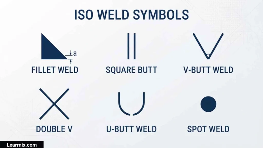
ISO welding symbols are used internationally and are associated with standards such as ISO 2553, which specifies symbolic representation of welded joints on technical drawings.
ISO and AWS systems have the same basic goal: to communicate welding requirements clearly. However, their conventions can differ in areas such as reference lines, symbol placement, arrow-side interpretation, and supplementary information.
When reading an ISO drawing, use the ISO conventions specified by the applicable document instead of automatically applying AWS rules.
This is particularly important for engineers, inspectors, manufacturers, and fabricators working with international suppliers or technical drawings from different regions.
FAQ
What is the most common weld symbol?
The fillet weld symbol is one of the most frequently encountered welding symbols. Fillet welds are widely used for T-joints, lap joints, and corner joints in fabrication and manufacturing.
What does a triangle mean in welding symbols?
A triangular shape is commonly used to illustrate a fillet weld symbol. However, the formal welding symbol used on an engineering drawing follows the applicable drafting standard and should not be confused with an ordinary Unicode triangle.
What is the difference between AWS and ISO weld symbols?
AWS and ISO welding-symbol systems have the same general purpose but use different conventions in some areas. Their reference-line and symbol-placement rules can differ, so the standard specified on the drawing should be followed.
How do you identify the size of a weld from its symbol?
Weld size is usually communicated through a dimension positioned according to the applicable welding-symbol standard. The number must be interpreted together with the symbol and its location rather than read as a standalone value.
Do weld symbols have Unicode characters?
Most formal welding symbols used in engineering drawings are graphical drafting symbols rather than ordinary Unicode characters. Some related geometric characters exist in Unicode, but they should not be treated as official substitutes for standardized welding notation.
Conclusion
Weld symbols provide a compact and practical language for communicating welding requirements on technical drawings. Learning the reference line, arrow, basic symbols, dimensions, and supplementary marks gives you the foundation needed to interpret most common welding callouts.
Fillet and groove weld symbols deserve particular attention because they occur frequently in fabrication and manufacturing. AWS and ISO systems provide established conventions, but they should not be treated as interchangeable. Always identify the applicable standard before interpreting an unfamiliar symbol.
The most reliable approach is to read the entire welding callout as one instruction. Consider the symbol, its position, dimensions, supplementary marks, drawing notes, and referenced standard together. With practice, even detailed welding drawings become much easier to understand accurately.

I am Michael Carter, an educational content creator who believes that knowledge has the power to transform lives.
I create resources focused on modern education, digital learning, and building essential skills for the future.
I love helping readers discover simple and effective ways to improve their learning journey.
Books by Michael Carter:
- Modern Education for Tomorrow’s World
- Learning Skills for Future Success
 Charlotte Anderson