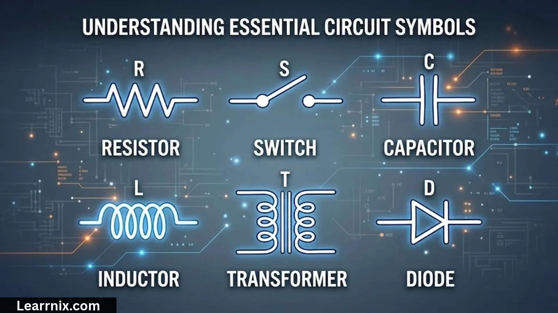
Circuit symbols are simple drawings used to represent electrical components in circuit diagrams. Instead of drawing every battery, wire, resistor, or switch as it looks in real life, engineers and students use standard symbols to show how these components connect and work together. Learning these symbols makes electrical diagrams easier to read, understand, and create.
There are many types of circuit symbols, including symbols for batteries, resistors, capacitors, switches, lamps, diodes, transistors, and measuring instruments. Each symbol represents a particular component or function. Some symbols look similar, so understanding their differences is useful when studying electronics, physics, or electrical engineering.
This guide explains circuit symbols, their names, meanings, and functions, with practical examples and easy-to-understand tables. You will also find information about schematic diagrams, logic gates, hydraulic symbols, and pneumatic symbols. Whether you are a student, a beginner in electronics, or someone looking for a circuit symbols chart, this article will help you understand the most important symbols.
Basic Circuit Symbols
Basic circuit symbols represent the essential components used to build and explain electrical circuits. These symbols help readers identify the power source, connecting wires, control devices, and electrical loads without needing detailed drawings.
Here are some common basic circuit symbols:
| Symbol | Name | Function |
| ───── | Wire | Connects components and provides a path for current |
| ─o/ o─ | Open switch | Breaks the circuit and stops current flow |
| ─o─o─ | Closed switch | Completes the circuit and allows current to flow |
| ─(X)─ | Lamp | Represents a light-producing component |
| ─///─ | Resistor | Limits current or divides voltage |
| ─| |─ | Capacitor | Stores electrical energy in an electric field |
| ─| |─ with unequal plates | Cell | Supplies electrical energy |
| ─| |─ with repeated long-short pairs | Battery | Represents multiple cells |
| ─(A)─ | Ammeter | Measures electric current |
| ─(V)─ | Voltmeter | Measures voltage |
| ─(M)─ | Motor | Converts electrical energy into mechanical motion |
These are simplified text representations, not exact substitutes for standardized schematic drawings. For example, a resistor is commonly drawn as a rectangle in IEC-style diagrams and as a zigzag in many ANSI-style diagrams.
When reading a circuit, start by locating the power source. Then follow the wires to identify switches, loads, and measuring instruments. This simple approach helps you understand how the circuit operates.
Common Circuit Symbols
Common circuit symbols appear in school science diagrams, electronic projects, electrical installations, and technical documents. Knowing them makes it easier to understand how different components affect current, voltage, and stored energy.
| Symbol or drawing convention | Component | What it does |
| Long and short parallel lines | Cell | Supplies electrical energy |
| Multiple long-short line pairs | Battery | Supplies energy from multiple cells |
| Rectangle or zigzag | Resistor | Controls current and voltage distribution |
| Rectangle or zigzag with an arrow | Variable resistor | Allows resistance to be adjusted |
| Two equal parallel plates | Capacitor | Stores charge and energy |
| One curved plate and one straight plate | Polarized capacitor | Represents a capacitor with polarity |
| Coil-shaped line | Inductor | Stores energy in a magnetic field |
| Triangle or diode-bar convention | Diode | Allows current primarily in one direction |
| Diode with arrows pointing outward | LED | Emits light when forward-biased |
| Two connected contacts | Switch | Opens or closes a circuit |
| Circle with a cross | Lamp | Converts electrical energy into light |
| Circle marked A | Ammeter | Measures current |
| Circle marked V | Voltmeter | Measures voltage |
The precise appearance of a symbol depends on the drawing standard and component type. Always check the diagram’s legend when one is provided.
Some symbols also have variations. A diode, for example, may be a standard rectifier diode, a Zener diode, a light-emitting diode, or a photodiode. These components share a basic diode structure but serve different purposes.
Electrical Circuit Symbols
Electrical circuit symbols are standardized visual representations of components used in electrical and electronic systems. They allow people to communicate circuit designs without relying on photographs or physical models.
Electrical symbols are commonly used in household wiring plans, industrial control systems, electronic devices, power distribution diagrams, and educational experiments.
Power Source Symbols
Power sources provide the energy needed for a circuit to operate.
- Cell: A single electrochemical source of electrical energy.
- Battery: Two or more cells connected together, or a battery assembly represented as a source.
- AC supply: Represents an alternating-current source.
- DC supply: Represents a direct-current source.
- Ground or reference: Identifies a common electrical reference point.
A ground symbol does not always mean a physical connection to the Earth. Depending on the diagram, it may indicate protective earth, chassis ground, or circuit reference ground.
Control And Protection Symbols
Control components determine when a circuit operates, while protection devices help limit damage under abnormal conditions.
- Switch: Opens or closes a current path.
- Push button: Provides momentary control when pressed.
- Fuse: Interrupts current when its element melts under excessive current.
- Circuit breaker: Opens a circuit when specified fault conditions occur.
- Relay: Uses an electrical control signal to operate contacts.
Output And Measuring Symbols
Output components use electrical energy to perform a task. Measuring components help monitor circuit behavior.
A lamp produces light, a motor creates mechanical movement, and a buzzer produces sound. An ammeter measures current and is connected in series in a typical current measurement setup. A voltmeter measures the potential difference between two points and is connected in parallel with the component being measured.
Understanding these groups makes electrical drawings easier to follow, especially when several components are connected in one system.
Circuit Symbols Physics
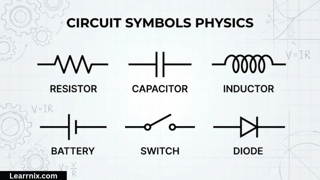
In physics, circuit symbols are used to explain electric current, potential difference, resistance, and energy transfer. Students encounter them when learning about simple circuits, Ohm’s law, series connections, parallel connections, and electrical power.
A circuit must have a complete conducting path for current to flow in a conventional closed-loop model. A power source provides electrical energy, wires form the connections, and components such as resistors or lamps transfer energy.
Important Physics Relationships
Three useful equations help explain how electrical components behave.
Ohm’s law:
V=IR
Here, V is voltage in volts, I is current in amperes, and R is resistance in ohms.
Electrical power:
P=VI
Power is measured in watts. For a resistor operating under the appropriate conditions, power can also be calculated using P=I2R or P=V2/R.
Charge and current:
I=Qt
Current is the amount of electric charge passing a point per unit time.
Circuit symbols allow students to apply these equations to diagrams without drawing realistic batteries, lamps, or measuring instruments.
For example, if a 6 V source is connected across a 3 Ω resistor in an ideal simple circuit, the current is:
I=VR=63=2A
This example shows how symbols and circuit calculations work together in physics.
Circuit Symbols and Functions
Each circuit symbol identifies a component with a particular electrical function. Understanding these functions is more useful than memorizing the appearance of symbols alone.
| Component | Main function | Typical use |
| Cell | Supplies electrical energy | Small battery-powered circuits |
| Resistor | Limits current or drops voltage | LEDs, sensors, and voltage dividers |
| Capacitor | Stores energy in an electric field | Filtering and timing |
| Inductor | Stores energy in a magnetic field | Filters and power converters |
| Diode | Controls the direction of current | Rectification and circuit protection |
| LED | Produces light | Indicators and displays |
| Transistor | Switches or amplifies signals | Digital and analog electronics |
| Switch | Controls circuit continuity | Manual and automated control |
| Relay | Operates contacts using a control signal | Control and isolation circuits |
| Fuse | Provides overcurrent protection | Electrical and electronic equipment |
| Motor | Converts electrical energy into motion | Fans, pumps, and machinery |
| Transformer | Transfers energy between coupled windings | Voltage conversion and isolation |
The same component may serve different purposes in different circuits. A resistor can limit current, divide voltage, or help set the operating point of a transistor. A capacitor can smooth a power supply, couple an audio signal, or establish a timing interval.
Always consider the component’s position and connections when interpreting its function.
Circuit Symbols and Names
Circuit symbols and names are often studied together because a recognizable drawing is easier to remember when paired with the correct component name.
The following reference list covers several frequently used components.
| Circuit symbol description | Symbol name |
| One long line and one short parallel line | Cell |
| Several alternating long and short parallel lines | Battery |
| Rectangular outline | Resistor, in IEC-style diagrams |
| Zigzag line | Resistor, in many ANSI-style diagrams |
| Two equal parallel plates | Capacitor |
| Coil or series of curved loops | Inductor |
| Contact with a gap | Open switch |
| Contacts joined together | Closed switch |
| Circle marked A | Ammeter |
| Circle marked V | Voltmeter |
| Circle containing a cross | Lamp |
| Diode symbol with outward arrows | Light-emitting diode |
| Three descending horizontal lines | Common ground-symbol convention |
Some diagrams use different conventions, so the drawing style should be interpreted in context. A symbol’s surrounding connections may also distinguish between similar components.
For instance, a resistor with an arrow crossing or pointing toward it usually represents an adjustable resistor. However, the exact symbol and meaning depend on the applicable standard.
Circuit Symbols and Meanings
The meaning of a circuit symbol explains what a component represents and how it behaves within a diagram. Some symbols are relatively straightforward, while others include extra lines, arrows, or labels to show special functions.
Here are several useful distinctions:
- Cell versus battery: A cell represents one electrochemical unit. A battery symbol usually represents multiple cells or a battery source.
- Open versus closed switch: An open switch shows a broken conducting path; a closed switch shows a connected path.
- Resistor versus variable resistor: A standard resistor has a fixed nominal resistance, while a variable resistor allows adjustment.
- Diode versus LED: A standard diode controls current direction, while an LED also emits light when operated correctly.
- Ground versus earth: A circuit ground may be a reference point, whereas protective earth is a safety connection to the grounding system.
- Ammeter versus voltmeter: An ammeter measures current, while a voltmeter measures voltage.
Arrows also matter. In electronic diagrams, arrows may indicate light emission, light reception, adjustable settings, or the direction of a signal or movement. Their meanings depend on the component symbol in which they appear.
Do not interpret an arrow in isolation. Look at the complete symbol and the diagram’s labels before deciding what it means.
Circuit Symbols Chart
A circuit symbols chart provides a quick reference for identifying components without reading long explanations. It is useful for students preparing for physics examinations, beginners learning electronics, and anyone reading a schematic.
| Category | Component | Main purpose |
| Power | Cell | Supplies electrical energy |
| Power | Battery | Provides a source of electrical energy |
| Connection | Wire | Joins components |
| Control | Switch | Opens or closes a circuit |
| Control | Push button | Provides momentary switching |
| Resistance | Resistor | Controls current and voltage |
| Resistance | Variable resistor | Adjusts resistance |
| Energy storage | Capacitor | Stores electrical energy in an electric field |
| Energy storage | Inductor | Stores energy in a magnetic field |
| Semiconductor | Diode | Conducts primarily in one direction |
| Semiconductor | LED | Produces light |
| Semiconductor | Transistor | Switches or amplifies signals |
| Measurement | Ammeter | Measures current |
| Measurement | Voltmeter | Measures voltage |
| Output | Lamp | Produces light |
| Output | Motor | Produces mechanical motion |
| Protection | Fuse | Interrupts excessive current |
| Protection | Circuit breaker | Disconnects a circuit under specified fault conditions |
How To Read A Circuit Symbols Chart
Start with the symbol’s shape, then check its label and connections. If the symbol includes an arrow, curved line, extra plate, or identifying letter, that detail may distinguish it from a similar component.
For example, two parallel plates usually represent a capacitor. If one plate is curved, the drawing may indicate a polarized capacitor. A diode symbol with two arrows pointing outward represents an LED in common schematic conventions.
When studying from a textbook, use its symbol chart as the primary reference because the textbook may follow a specific national or international standard.
Simple Circuit Symbols
Simple circuit symbols are the basic drawings needed to understand introductory electrical circuits. They usually include a cell, connecting wires, a switch, and a load such as a lamp or resistor.
A basic battery-powered lamp circuit contains four main elements:
- A cell or battery supplies electrical energy.
- Wires connect the components.
- A switch controls whether the conducting path is complete.
- A lamp converts electrical energy into light and heat.
When the switch is closed, the circuit forms a complete path and current can flow. When the switch is open, the conducting path is interrupted and the lamp goes out.
A resistor can replace the lamp in a simple demonstration circuit. In an idealized circuit, its current depends on the applied voltage and resistance according to Ohm’s law.
Simple circuit diagrams help learners understand how components work together. They also introduce important concepts such as current direction, voltage across components, and the difference between series and parallel connections.
Remember that a circuit symbol is a representation of a component, not a picture of its physical appearance.
Schematic Circuit Symbols
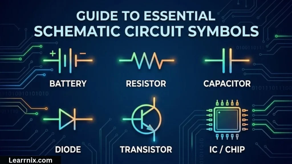
Schematic circuit symbols are used in electrical and electronic drawings to show components and their electrical connections. A schematic emphasizes how a circuit works rather than how the components are physically arranged on a board.
A circuit schematic may include resistors, capacitors, transistors, integrated circuits, connectors, power supplies, and ground references. Component labels such as R1, C1, Q1, and U1 are often used to identify individual parts.
For example:
- R1: Commonly identifies a resistor.
- C1: Commonly identifies a capacitor.
- D1: Commonly identifies a diode.
- Q1: Commonly identifies a transistor.
- U1: Commonly identifies an integrated circuit.
These designators are common conventions, not universal guarantees. A drawing’s legend or project documentation takes priority.
Why Schematic Symbols Matter
Schematic symbols make it possible to discuss a circuit’s behavior without focusing on physical layout. A resistor drawn near the top of a page may be mounted anywhere on the actual circuit board, provided the electrical connections remain correct.
A schematic also shows important relationships between components. For example, a resistor and LED connected in series may form an indicator circuit, while a capacitor connected across a supply may help reduce voltage fluctuations.
Connection Points And Crossings
Lines usually represent electrical connections. A junction dot commonly indicates that three or more wire segments are electrically joined. Crossing lines without a junction dot may indicate separate conductors in some drawing conventions.
Because standards vary, check the diagram’s conventions rather than assuming every crossing has the same meaning.
Circuit Symbols Resistor
A resistor is a passive electrical component that opposes current flow. It is widely used to limit current, divide voltage, establish transistor operating conditions, and control signals.
There are two common resistor-symbol styles:
- Rectangle: Used in IEC-style circuit diagrams.
- Zigzag line: Used in many ANSI-style diagrams.
These represent the same general component. The difference is mainly a matter of drawing convention.
Types Of Resistor Symbols
| Component | Symbol description | Function |
| Fixed resistor | Rectangle or zigzag | Provides a set nominal resistance |
| Variable resistor | Resistor with an adjustment arrow | Allows resistance to be changed |
| Potentiometer | Resistor with a movable contact | Provides an adjustable voltage divider |
| Thermistor | Resistor with a temperature-related marking | Changes resistance with temperature |
| Light-dependent resistor | Resistor with light arrows directed toward it | Changes resistance with incident light |
The precise symbols for specialized resistors may differ by standard. Use the relevant schematic legend when interpreting temperature-sensitive or light-sensitive components.
How A Resistor Works
Resistance is measured in ohms, represented by the Greek letter omega: Ω. A resistor limits current according to the voltage across it and its resistance, assuming the circuit conditions are suitable for Ohm’s law.
For example, if a 9 V supply is connected across a 1 kΩ resistor, the ideal current is:
I=91000=0.009A=9mA
In a real circuit, other components and source resistance may affect the current.
Resistor values are often marked with colored bands or printed numbers. The symbol itself generally does not show the resistance value, so the schematic may include a label such as 220 Ω, 1 kΩ, or 10 kΩ.
Circuit Symbols Cell
A cell is a source of electrical energy that converts stored chemical energy into electrical energy. In a circuit diagram, a cell is usually represented by two parallel lines of unequal length.
The longer line conventionally indicates the positive terminal, while the shorter line indicates the negative terminal. This distinction helps identify the source polarity in a direct-current circuit.
Cell And Battery Symbols
A single cell is represented by one long-short pair of parallel lines. A battery symbol commonly shows several alternating long and short lines to represent multiple cells.
| Feature | Cell | Battery |
| Basic representation | One long-short line pair | Multiple long-short pairs |
| Purpose | Provides electrical energy | Provides electrical energy from a battery assembly |
| Common examples | Single electrochemical cell | Multi-cell battery pack |
| Polarity | Positive and negative terminals | Positive and negative terminals |
A cell can be connected in series with other cells to increase the total voltage. For ideal cells connected in series in the same direction, their voltages add. Connecting cells in parallel requires compatible voltage and chemistry and must follow the manufacturer’s instructions.
How A Cell Works In A Circuit
When a cell is connected to a complete conducting circuit, it can drive current through the components. The amount of current depends on the source voltage, circuit resistance, and other electrical characteristics.
For example, a cell connected to a switch and lamp can form a simple lighting circuit. Closing the switch completes the conducting path; opening it interrupts the path.
The cell symbol is common in physics textbooks because it makes polarity and the source of electrical energy easy to recognize.
Logic Circuit Symbols
Logic circuit symbols represent digital components that process binary signals. These circuits operate using logical states commonly described as 0 and 1, which often correspond to different voltage ranges in a particular digital system.
Logic gates are used in computers, calculators, control systems, digital displays, and many electronic devices.
| Logic gate | Common notation | Function |
| AND | AND | Outputs 1 when all inputs are 1 |
| OR | OR | Outputs 1 when at least one input is 1 |
| NOT | NOT | Reverses the input state |
| NAND | NAND | Outputs 0 only when all inputs are 1 |
| NOR | NOR | Outputs 1 only when all inputs are 0 |
| XOR | XOR | Outputs 1 when the inputs differ |
| XNOR | XNOR | Outputs 1 when the inputs are the same |
These names describe the logical behavior, while the actual gate shapes depend on the symbol standard used. IEEE-style logic symbols and traditional distinctive gate shapes may look different.
Basic Logic Gate Examples
An AND gate with two inputs produces an output of 1 only when both inputs are 1.
An OR gate produces an output of 1 if either input is 1 or both inputs are 1.
A NOT gate has one input and produces the opposite logical state.
A NAND gate is an AND gate followed by logical inversion. A small circle, often called an inversion bubble, may appear at the output of a logic symbol to indicate inversion. Similar bubbles can appear on inputs to show active-low behavior.
Logic symbols help engineers understand digital operations without drawing the internal transistor-level circuitry of every gate.
Hydraulic Circuit Symbols
Hydraulic circuit symbols represent components in systems that use pressurized liquid to transmit power. These symbols are used in machinery, industrial equipment, construction vehicles, and manufacturing systems.
Hydraulic schematics commonly show pumps, reservoirs, valves, cylinders, motors, filters, and connecting lines.
| Component | Function |
| Hydraulic pump | Supplies fluid flow to the system |
| Reservoir or tank | Stores hydraulic fluid |
| Directional control valve | Directs fluid through selected paths |
| Pressure relief valve | Limits pressure by opening a relief path |
| Hydraulic cylinder | Converts fluid power into linear motion |
| Hydraulic motor | Converts fluid power into rotary motion |
| Filter | Removes contaminants from the fluid |
| Check valve | Allows flow in one direction and restricts reverse flow |
Hydraulic symbols are generally standardized, but their exact shapes and details depend on the applicable drawing standard, such as ISO 1219.
A directional control valve may be represented by adjacent squares showing different flow paths and operating positions. Arrows and blocked-end markings indicate the possible direction of fluid movement.
A hydraulic cylinder symbol identifies a linear actuator, while a hydraulic motor represents rotary motion. These symbols help technicians understand how pressure and flow produce movement.
Hydraulic schematics should be interpreted as complete systems. The pump, valves, actuators, reservoir, and return lines work together, so understanding one symbol alone may not explain the entire machine’s behavior.
Pneumatic Circuit Symbols
Pneumatic circuit symbols represent components in systems that use compressed air or another gas to produce and control movement. They are common in factory automation, packaging equipment, production lines, and pneumatic tools.
Although pneumatic and hydraulic schematics may use similar conventions, they represent different working fluids and operating conditions.
| Component | Function |
| Compressor | Supplies compressed air |
| Air preparation unit | Filters and may regulate or lubricate the air supply |
| Directional control valve | Directs air to selected ports |
| Pressure regulator | Controls downstream air pressure |
| Pneumatic cylinder | Produces linear motion |
| Pneumatic motor | Produces rotary motion |
| Flow control valve | Adjusts airflow |
| Check valve | Permits flow primarily in one direction |
| Exhaust silencer | Reduces noise from escaping air |
Understanding Pneumatic Valve Symbols
Directional control valves are often represented by a row of connected squares. Each square shows one valve position, while arrows and blocked lines indicate how the ports connect in that position.
Valve descriptions such as 3/2 and 5/2 refer to the number of ports and switching positions. A 3/2 valve has three ports and two positions, while a 5/2 valve has five ports and two positions.
A spring symbol may indicate spring return, while a manual actuator, solenoid, or pneumatic pilot symbol shows how the valve is operated.
These details help readers understand how a cylinder extends, retracts, or stops when the control valve changes position.
For accurate interpretation, consult the relevant pneumatic drawing standard and the equipment manufacturer’s documentation.
Circuit Symbols And Their Practical Applications
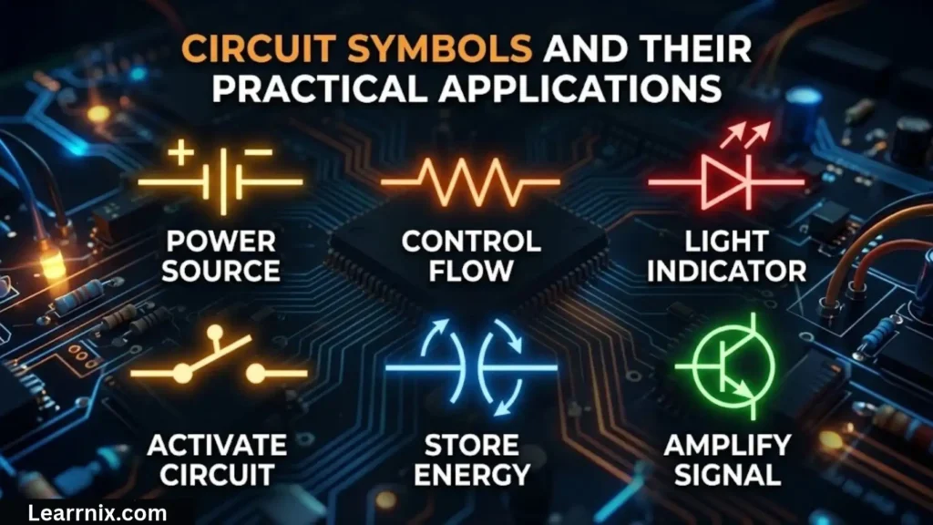
Circuit symbols are useful in many areas, from classroom experiments to industrial equipment. Their main advantage is that they provide a consistent way to communicate a system’s design.
Education And Physics
Students use circuit symbols to draw simple series and parallel circuits, calculate resistance, and understand voltage and current. Standard symbols also make examination diagrams easier to read.
Electronics Design
Electronic engineers use schematic symbols to plan circuits containing resistors, capacitors, transistors, diodes, sensors, and integrated circuits. The schematic provides a logical representation of the electrical connections.
Electrical Installation
Electrical plans use symbols to identify switches, lighting points, outlets, protective devices, and other installation components. The exact conventions depend on the applicable electrical drawing standard and local requirements.
Industrial Automation
Hydraulic and pneumatic symbols help technicians understand fluid-power systems, troubleshoot faults, and identify the roles of valves, pumps, actuators, and other components.
Tips For Reading Circuit Diagrams
- Identify the power source and its polarity.
- Follow the connecting lines and junctions carefully.
- Check component labels and values.
- Distinguish between open and closed contacts.
- Look for arrows, polarity markings, and other special features.
- Read the drawing legend when the symbol style is unfamiliar.
- Use the correct standard for the diagram’s electrical, hydraulic, or pneumatic system.
These habits help reduce mistakes and make complex diagrams easier to interpret.
Frequently Asked Questions
What are circuit symbols used for?
Circuit symbols represent electrical and electronic components in diagrams. They help people understand connections, identify component functions, and communicate circuit designs without drawing each component realistically.
What are the most common circuit symbols?
Common symbols represent cells, batteries, wires, switches, resistors, capacitors, inductors, diodes, LEDs, transistors, lamps, and measuring instruments such as ammeters and voltmeters.
What is the difference between a cell and a battery symbol?
A cell symbol usually contains one pair of parallel lines of unequal length. A battery symbol commonly contains several alternating long and short line pairs to represent multiple cells or a battery assembly.
Why do resistor symbols look different in some diagrams?
Resistors are commonly shown as rectangles in IEC-style diagrams and as zigzag lines in many ANSI-style diagrams. Both conventions represent the same general component, although the surrounding notation may differ.
Are electrical, hydraulic, and pneumatic symbols the same?
No. They belong to different types of technical diagrams. Electrical symbols represent electrical components, hydraulic symbols represent pressurized-liquid systems, and pneumatic symbols represent compressed-gas systems. Some drawing conventions may look similar, but their meanings depend on the relevant standard.
Conclusion
Circuit symbols provide a simple and consistent way to represent electrical components, electronic devices, and fluid-power systems. Learning their names, meanings, and functions makes it easier to understand diagrams and recognize how different components work together.
Basic electrical symbols such as cells, batteries, resistors, switches, capacitors, and diodes are a good starting point. As your knowledge develops, schematic symbols and logic gates can help you understand electronic circuits, while hydraulic and pneumatic symbols introduce the principles behind industrial control systems.
For the best results, keep a circuit symbols chart nearby, practise identifying components in real diagrams, and check the relevant standard whenever a symbol is unfamiliar. Understanding the connections between symbols is just as important as recognizing their shapes.

I am Michael Carter, an educational content creator who believes that knowledge has the power to transform lives.
I create resources focused on modern education, digital learning, and building essential skills for the future.
I love helping readers discover simple and effective ways to improve their learning journey.
Books by Michael Carter:
- Modern Education for Tomorrow’s World
- Learning Skills for Future Success
 Charlotte Anderson
 Daniel Harper